The infrastructure system in the United States is aging now. The existing roads, bridges, water systems and other infrastructure facilities that were constructed a long time ago need complete renovation. Hence, the need to complete Infrastructure projects at faster speed while achieving lower prices compared to traditional methods has become a necessity.
- Traditional infrastructure design relied on disconnected workflows:
- Engineers produced highway drawings in CAD
- Structural teams designed bridges in isolation
- Utility coordinators reconciled conflicts through plan reviews
Conflicts surfaced during construction. Excavators struck unmarked gas lines. Bridge clearances failed to align with roadway grades. Each issue triggered change orders. Delays followed. Budgets expanded.
BIM Infrastructure Projects USA are changing this pattern. The team creates one complete digital model, which holds all components, including drainage pipes and overhead power lines. The highway engineer modifies a vertical curve, which causes the system to change bridge heights and utility depths, together with slope intersection points.
The shift is accelerating:
- The General Services Administration requires BIM for federal buildings
- California, New York, and Texas mandate BIM for state-funded infrastructure
- The Federal Highway Administration promotes adoption through research programs
Projects using BIM finish roughly 20% faster than traditional delivery Design errors drop by 30%. Large highway reconstructions adopt BIM out of necessity. Smaller regional projects still depend on 2D workflows.
Understanding BIM in Infrastructure Development
BIM in Construction Projects means different things across disciplines. Building architects coordinate walls, floors, and mechanical systems inside fixed envelopes. Infrastructure teams model linear assets that extend for miles. These assets interact with terrain that changes continuously. Utilities remain buried and unseen.
Infrastructure BIM handles conditions buildings do not face. A highway reconstruction can span 20 miles. It can cross multiple watersheds. It can require relocation of dozens of utility systems. Traffic must continue throughout construction.
What Infrastructure BIM Modeling Actually Does
It creates a single environment where all information exists together:
- Engineers model terrain from survey data
- Roadway alignments follow existing ground surfaces
- Structural teams place bridges where grades require them
- Utility coordinators route water, sewer, gas, and fiber optic lines around structures
- Environmental specialists overlay wetlands, habitats, and protected zones
When a drainage engineer reroutes a storm sewer to avoid bedrock, the model shows conflicts with the proposed water main. When structural engineers deepen a bridge foundation, the model reveals impacts on underground utilities.
BIM in Planning and Feasibility Studies
Feasibility studies decide whether projects proceed. Traditional feasibility analysis separated responsibilities. Engineers evaluated technical feasibility. Cost analysts reviewed budgets. Environmental specialists assessed impacts independently.
How BIM Creates A Shared Analytical Foundation
Teams build preliminary models before detailed design begins. These models integrate GIS terrain data, geotechnical boring logs, environmental constraint maps, and conceptual layouts. The consolidated model becomes the testing ground for viability.
Project teams’ model different alignment options for a new highway corridor:
- One alignment minimizes environmental impact but requires costly bridges
- Another reduces structures but crosses wetlands that require mitigation
- A third follows existing corridors but demands extensive utility relocation
The BIM model allows analysts to quantify trade-offs using the same digital baseline.
Where Cost Estimation Gets Dramatically Better
Traditional estimating required manual quantity takeoffs from 2D drawings services. BIM extracts quantities directly from geometry. The model contains concrete volumes for bridge piers, linear footage of drainage pipe, and earthwork quantities generated by grading plans.
Feasibility estimates once carried Why Visualization Builds Stakeholder Trust by including sufficient geometry for reliable quantity extraction.
Enhancing Design Accuracy with BIM Models
Design errors create costly disruptions. Structural drawings sometimes show bridge clearances that conflict with roadway profiles. Contractors halt work until engineers resolve discrepancies.
How Parametric Modeling Eliminates Coordination Errors
Traditional CAD treated each view independently. Plan views, profiles, and cross-sections existed as separate drawings. A vertical alignment change required manual updates across all views. Missed updates caused contradictions.
BIM maintains single-source geometry:
- The roadway alignment exists as a parametric object
- Vertical curve changes update every view automatically
- Cross-sections regenerate, quantities recalculate, and clash checks rerun
Complex infrastructure contains hundreds of interdependent components. This reduction prevents dozens of conflicts before construction begins.
Why Visualization Builds Stakeholder Trust
BIM models support interactive visualization. During public meetings, teams navigate 3D models and show stakeholders how interchanges will appear from multiple viewpoints. When residents ask about neighborhood impacts, engineers place the virtual camera at that location and display the view.
The I-4 Ultimate project in Orlando used 3D visualization during community engagement. Teams showed residents completed corridor views, demonstrated traffic flow through new interchanges, and adjusted perspectives live in response to questions.
Improving MEP and Structural Coordination
Infrastructure projects consolidate multiple systems like structure, MEP, etc., into limited space. An urban highway reconstruction must fit in the drainage systems, relocated utilities, electrical conduits, gas mains, fiber networks, and structural elements inside rights-of-way that may measure only 100 feet wide.
How Clash Detection Services Automate Conflict Identification
Each discipline produces detailed system models:
- Structural engineers model beams, columns, and foundations
- MEP designers model pipes, ducts, and conduits
- Models combine in a shared coordination environment
Software analyzes geometry and generates clash reports. Reports list coordinates, affected components, and visual references. Coordination teams review conflicts, assign responsibility, and track resolution.
The Financial Impact Of Finding Conflicts In Design
Studies of large MEP projects show hundreds of conflicts detected during design. Model-based resolution takes hours of engineering time. Field resolution requires work stoppages, redesign, approvals, and rework.
Projects using comprehensive clash detection save approximately 10% of total contract costs through prevention. Construction proceeds without unexpected conflicts. Crews maintain productivity. Milestones remain achievable.
Why Utility Coordination Deserves Special Attention
Underground utility records are generally inaccurate. As-built drawings may have missing or outdated data. Survey teams verify locations using ground-penetrating radar and test for excavations. This verified data is incorporated into the BIM model and works as an accurate coordination baseline.
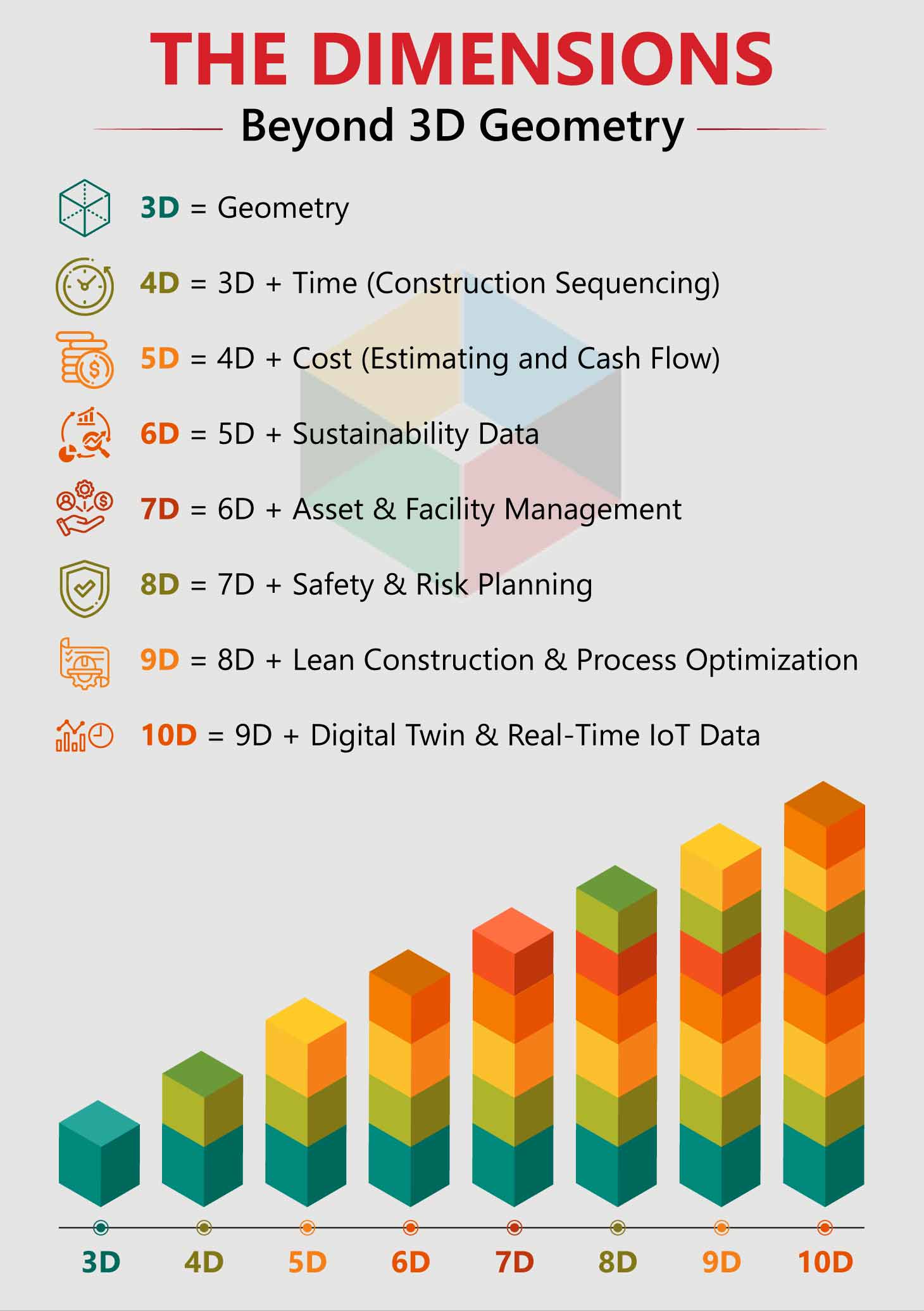
BIM for Construction Scheduling and Cost Control (4D & 5D)
Construction managers manage complex sequencing constraints. Highway reconstruction projects need traffic maintenance. Considering the fact, project teams demolish pavement, install drainage, build foundations, and construct roadway sections.
What 4D BIM Reveals About Construction Sequences
Time-linked models create visual simulations. Components receive installation dates. Software generates day-by-day construction animations. Managers observe sequencing conflicts before work begins.
A 4D simulation can reveal traffic detour conflicts with excavation timing. It can show material deliveries overlapping active work zones. Construction requires staging areas, crane access, and equipment routes. 4D models confirm whether space exists when required.
What 5D Integration Means for Cost Control
Cost data links to each model component. Materials, labor, and equipment costs attach directly to geometry. As sequences advance, 5D analysis calculates period-specific cash flow.
Teams compare construction methods. Precast bridge elements may cost more per unit than cast-in-place options. Faster installation can offset higher unit costs through schedule compression and reduced traffic management expenses.
Integration of Reality Capture and Existing Conditions
Infrastructure renovations must match existing conditions. Bridge reconstruction planning and execution require accurate documentation of geometry, deformation, deterioration, and as-built conditions that generally differ from original drawings.
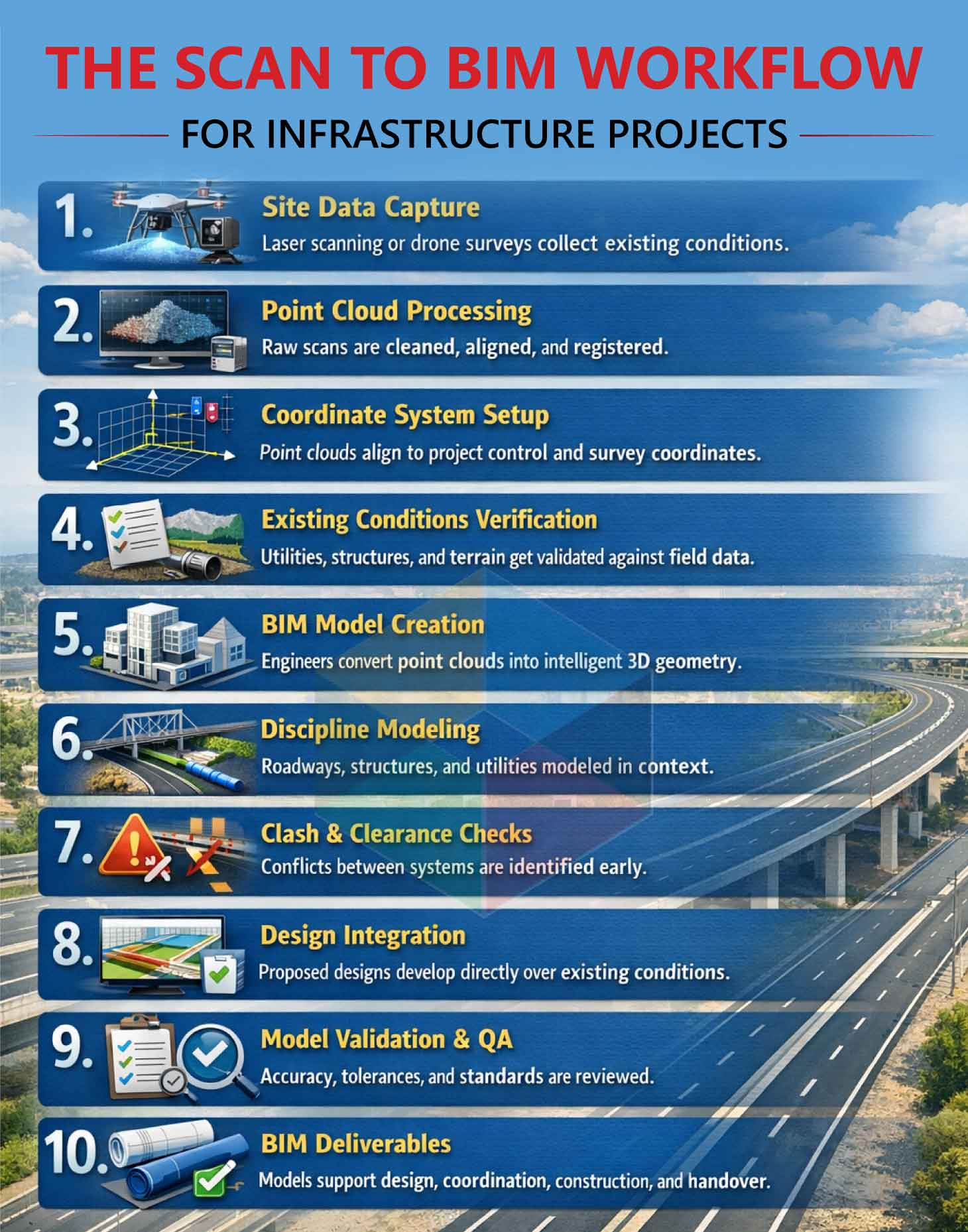
How Laser Scanning Captures Existing Conditions
Surveyors deploy tripod-mounted scanners or drones. These systems collect millions of spatial data points. The resulting point cloud records visible surfaces with millimeter-level precision.
The Scan to BIM Workflow
Modelers import point clouds and trace BIM geometry that matches scanned conditions. A scanned bridge becomes a model reflecting actual dimensions. Engineers design modifications based on verified conditions.
Addressing the Underground Utility Challenge
Utility records rarely reflect reality. Drawings may be missing or incorrect after decades of modifications. So, surveyors use ground penetrating radar and vacuum-based excavation to verify locations. Verified findings enter BIM models and establish accurate utility baselines.
Supporting Sustainability and Compliance
Infrastructure agencies now require detailed proof of environmental performance. LEED projects must document compliance for energy use, water systems, materials, and site conditions.
How BIM Consolidates Sustainability Documentation
Environmental data embeds directly in models. Material specifications include environmental product declarations. Energy analysis tools read geometry from the model. Water system components carry efficiency and flow data. Teams generate compliance reports directly from model data.
Carbon Tracking at Multiple Scales
Material-level tracking calculates embodied carbon using quantities and EPD data. A bridge deck’s footprint equals concrete volume multiplied by EPD carbon intensity. The model aggregates component calculations into total project carbon values.
Two bridge designs may serve identical functions. BIM-based carbon analysis can show one option produces 20% lower lifetime emissions. Agencies balance cost, performance, and environmental impact using quantifiable data.
BIM for Asset Management and Facility Operations
Project closeout traditionally involved paper manuals and static drawings. Operations teams received fragmented information that was difficult to maintain.
How Digital Twins Transform Operations Handover
Construction models transition into operational digital twins. Each asset includes specifications, installation dates, warranties, and maintenance requirements. During the servicing of valve data, like manufacturer information, part numbers, and maintenance records is pulled from the digital twin.
IoT Integration for Real-Time Monitoring
Embedded sensors can track pressure, temperature, vibration levels, and flow rates across the system. Data streams into the digital twin. Dashboards show asset status and emerging performance trends.
Predictive Maintenance Capabilities
Gradual vibration increases can signal bearing failure. Traditional maintenance responds after breakdown. Predictive maintenance schedules repairs during planned downtime. Emergency costs decrease. Service disruptions decline.
Case Studies: BIM Success Stories in US Infrastructure
I-4 Ultimate: Coordination at Unprecedented Scale
The I-4 Ultimate project covered a 21-mile stretch of Interstate 4 through downtown Orlando. The scope included 15 major interchanges and 145 bridges.
Teams used BIM for coordination and visualization. Interchange geometries included four vertical levels. Precise coordination was required between structures, roadways, and utilities.
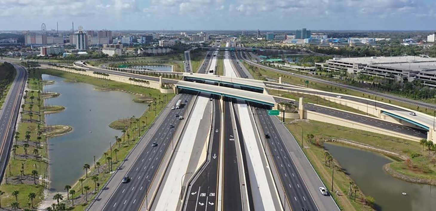
Clash detection identified conflicts during design. Issues were resolved before mobilization. 4D sequencing supported traffic management planning. Comparative analysis estimated $1.375 billion in lifecycle savings, roughly 35% of total project costs over the 40-year concession period.
Federal Highway Administration Bridge Demonstrations
The FHWA implemented BIM across multiple bridge projects. Fabricators working from models began shop drawing development earlier. Requests for information decreased. Field modifications declined because fabricated components matched design intent.
Challenges in BIM Adoption for Infrastructure Projects
Despite clear technical benefits, adoption often slows due to practical constraints inside firms and across project teams.
Software Interoperability Remains the Persistent Technical Barrier
Infrastructure teams use different platforms. Civil engineers use Civil 3D. Structural teams rely on STAAD or RISA. MEP designers use Revit. Geotechnical specialists work in proprietary tools. File incompatibility forces manual data translation.
Industry Foundation Classes aim to address interoperability. Implementation varies by platform. Some proprietary data fails to transfer accurately.
Initial Investment Costs Create Adoption Barriers
Small regional firms face high entry costs. BIM software licenses cost thousands per user each year. Workstations and servers add hardware expenses. Training demands months of practice and continuous development. Initial investments are huge compared to generating a materialized return in a project.
The Skills Gap and Cultural Resistance
Many infrastructure professionals trained before BIM adoption. Firms must hire recent graduates or retrain experienced staff. Engineers with decades of experience resist workflows that invalidate established practices.
How Infrastructure Firms Can Get Started with BIM
Adoption works best when firms approach BIM incrementally rather than attempting full-scale transformation at once.
Start with a Pilot Project
Choose a mid-size project with manageable complexity. The scope should demonstrate value without excessive risk. Select team members open to digital workflows:
- Limited scope contains risk
- Teams gain practical experience
- Documented success builds internal confidence
- Lessons prevent errors on larger projects
Invest in Training Before Project Launches
Enroll staff in software-specific training. Focus on tools used in active projects. Software companies like Autodesk and Bentley provide infrastructure-focused training programs. Budget for continued training beyond initial courses.
Partner with Infrastructure-Specialized Consultants
Infrastructure-focused BIM consultants help define standards and workflows. Select partners with civil and transportation experience rather than building-centric backgrounds.
Develop Organization-Wide Standards
Establish standards after initial projects stabilize. Define model structure, naming conventions, phase-specific detail levels, and deliverable formats. Standards allow knowledge reuse across projects.
Conclusion
Building Information Modeling (BIM) has become a required standard for all infrastructure work in the United States. The digital delivery method results in rapid project completion and reduced costs while delivering better quality results.
Adoption remains uneven. Smaller firms face cost and training barriers. Cultural resistance persists. The direction remains clear. Government mandates expand. Clients specify BIM deliverables. Competitive pressure increases with the growing complexity.
Firms that begin adoption now gain long-term positioning advantages. Future infrastructure will not rely on legacy methods. Digital coordination, predictive analysis, and lifecycle planning define the next phase of delivery. BIM provides the structural foundation for that shift.