Construction teams lose money every time they send a crew back to a site to re-measure something. Studies on global project performance show rework consumes 4 to 10 percent of total project cost, and in many projects that figure climbs past 11 percent. Most of this waste traces back to a single root cause: inaccurate existing-condition data. Manual tape measurements, hand sketches, and isolated photos leave gaps that surface only after design work begins.
Scan to CAD services close that gap by capturing every surface of a building in a single visit, converting it into precise drawings teams can trust from day one. This article explains how the workflow functions, why site revisits happen so often, and how accurate reality capture data changes the economics of a project.
What Are Scan to CAD Services?
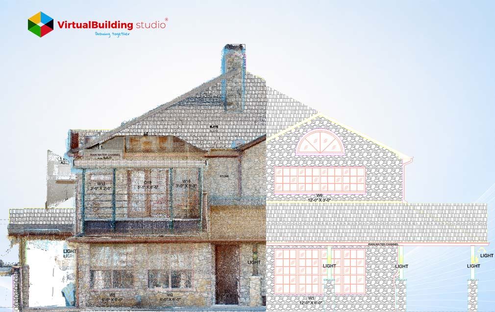
Scan to CAD Services help convert 3D laser scans and photogrammetry data into dimensioned CAD drawings that represent a building exactly as it stands today. Field teams capture existing conditions using laser scanners or cameras, generating dense point clouds that record walls, floors, ceilings, columns and MEP systems to millimeter level precision. Drafters then process this data into floor plans, elevations, sections, reflected ceiling plans and MEP layouts inside tools such as AutoCAD and AutoCAD Plant 3D.
Autodesk frames this reality computing pipeline in three stages.
- Scanners and cameras handle the capture stage.
- Registration and cleanup happen during processing.
- Drafters and modelers then attach the finished point cloud into design software to build CAD or BIM outputs.
Scan to CAD services sit specifically in that final stage, turning raw scan data into documentation that architects and engineers can act on immediately.
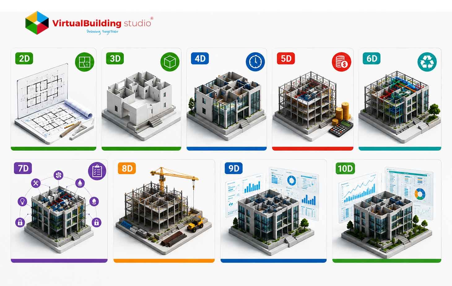
Scan to BIM services extend this same pipeline further, converting point clouds into parametric 3D elements instead of flat drawings.
- Scan to CAD drafting produces 2D files such as DWG, DXF, and PDF.
- Point Cloud to BIM workflows instead produce walls, slabs, ducts and equipment as intelligent objects carrying metadata for coordination and facility management.
- Many firms combine both: 2D drawings support permitting and documentation; on the other hand 3D models support clash detection and long-term asset management.
Accuracy separates this workflow from manual surveying. Modern laser scanners achieve precision within 2 to 3 millimeters, compared with 6 to 12 millimeters for handheld measurement tools. Published tolerance tables for scan-derived documentation cite around plus or minus 6 millimeters for general architectural drawings, tightening to 1.5 to 3 millimeters for fabrication-ready detail. That precision is what makes Scan to CAD Conversion reliable enough to eliminate guesswork later in a project.
Why Construction Projects Require Site Re-Visits
Rework rarely stems from bad materials. It stems from bad information.
Research synthesized by PlanRadar across 15 countries found that most clients experienced rework costs above 11 percent of project budget before adopting digital documentation tools. Miscommunication alone accounts for roughly 26 percent of rework whereas inaccurate or outdated data drives another 14 to 22 percent.
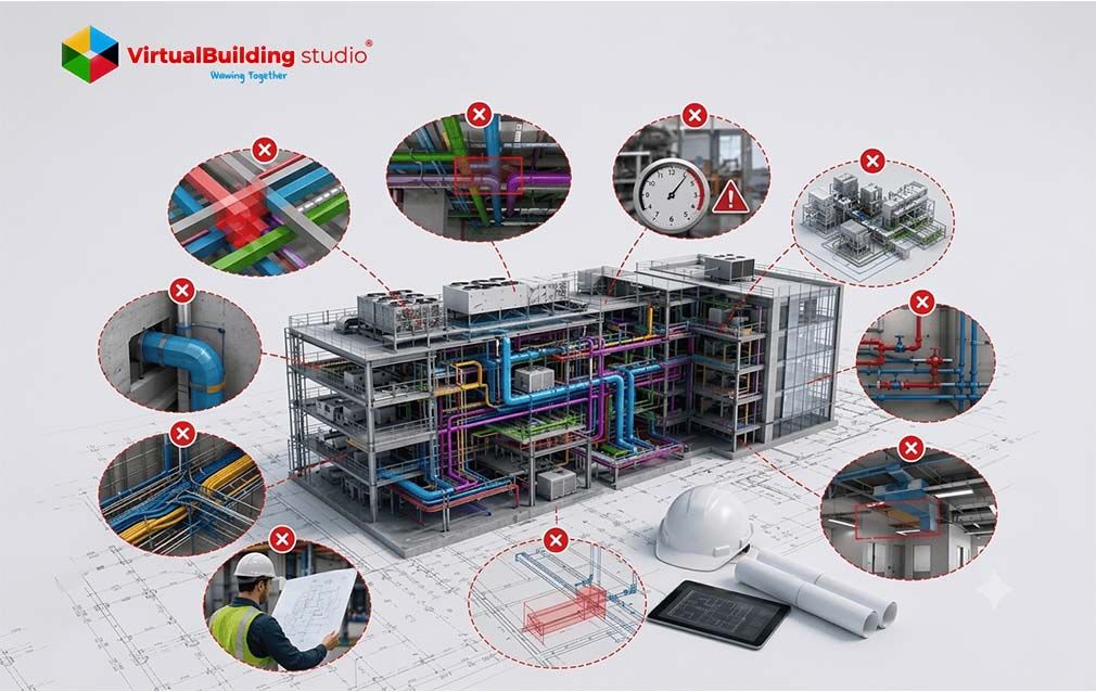
When drawings do not match reality, crews return to the site to verify dimensions and resolve conflicts that were invisible on paper.
Traditional as-built documentation carries built-in limitations that make this cycle worse. Manual surveying methods rely on a surveyor choosing which dimensions to record, which means entire categories of conditions get skipped.
- Ceiling cavities and above-grid MEP runs that are hard to reach
- Irregular geometry that resists standard tape measurements
- Concealed structural elements that only appear during demolition
- Minor deviations between drawn and built dimensions
Industry sources tracking as-built accuracy in North American AEC practice report average error rates of 12 to 15 percent for manually produced documentation. Every one of those errors becomes a candidate for a future site visit.
Renovation planning intensifies this problem because legacy drawings age poorly. Research on retrofit projects notes that as-designed BIM models diverge from actual conditions due to undocumented changes and modeling errors made over the life of a building. Teams then schedule repeated mobilizations to confirm dimensions and check hidden conditions, a costly workaround in facilities with limited access windows such as hospitals or heritage buildings.
How Accurate Scan to CAD Services Eliminate Site Re-Visits
The re-visit problem exists because traditional documentation is incomplete. Accurate Scan to CAD services solve it by capturing complete existing conditions in a single mobilization instead of a series of partial measurements. Scanners can cover thousands of square feet in minutes, and full buildings in hours, cutting field time by up to 80 percent compared with manual methods.
Once a point cloud is registered, designers no longer need to return to the site to check a missed measurement. They extract dimensions directly from the point cloud using ReCap Pro, AutoCAD, Revit, or Navisworks. That shift changes what a site visit is for. Instead of primary data collection, physical visits become targeted inspections for the rare condition that genuinely needs eyes on it.
Accuracy compounds this benefit. Because laser scanning delivers 2 to 3 millimeter precision and captures every visible surface at once. Drawings built through 3D Laser Scanning Services carry far less error than manual as-builts.
PlanRadar's research shows design-related errors account for 1 to 9 percent of total project cost, and its customer data indicates digitization can cut rectifications by more than 50 percent.
Grounding design decisions in accurate geometry removes many of those errors before they happen.
Cloud access extends the benefit beyond the field team.
- Autodesk Construction Cloud lets teams upload processed scans directly into Autodesk Docs.
- Anyone can measure and mark up point clouds through a browser.
- Dimensional checks, clash reviews, and coordination meetings can happen virtually using the point cloud instead of requiring another site trip.
Progressive scanning adds one more layer for complex facilities. Scanning at multiple points during construction or renovation captures conditions that were hidden during earlier passes, such as ducts and pipes behind finished walls. That combined dataset becomes a long-term reference for future maintenance and renovation work, cutting the need for exploratory demolition down the line.
Key Reasons for Site Re-Visits and Scan to CAD Solutions
Scan to CAD Workflow - From Laser Scan to Accurate Drawings
The re-visit reductions described above depend entirely on how the workflow is executed. Four stages determine whether a Scan to CAD project delivers the accuracy it promises.
Capture
Field teams identify the intended use of the data before scanning begins, whether that is renovation planning, MEP coordination, or fabrication support. They establish survey control points, plan scan positions to avoid blind spots, and capture overlapping coverage so registration has enough data to work with.
Process
Raw scans get registered into one coordinate system using shared targets or overlapping geometry. Software such as ReCap Pro indexes individual scan files into RCS files and assembles them into a single RCP project. Processing also includes noise filtering and basic classification to separate surfaces of interest from clutter. Weak registration at this stage introduces distortions that undermine every drawing built afterward.
Drafting and Modeling
The registered point cloud gets attached inside AutoCAD, Revit, or Navisworks, where it becomes the spatial reference for new linework. Drafters trace the point cloud to produce architectural floor plans, elevations, sections, reflected ceiling plans, and detailed MEP layouts. Plant-focused projects use tools like PointSense Plant to extract tie-in points and generate isometric drawings ready for fabrication. Point Cloud to CAD conversion at this stage turns raw geometry into documentation a design team can actually use.
Quality Assurance
Finished drawings get checked against the source point cloud before delivery. Reviewers spot-check critical dimensions such as structural grids and major openings, overlay CAD geometry onto the point cloud to confirm alignment, and adjust anything that falls outside defined tolerance bands. This step is what allows a firm to trust Laser Scan to CAD deliverables enough to build a project schedule around them.
Each stage builds on the one before it, so a weak link anywhere breaks the accuracy chain. When every stage holds, the drawings that come out the other end are accurate enough to replace a return trip to site. That reliability is exactly what turns the workflow into measurable project benefits.
Key Benefits of Scan to CAD Services
Each stage of that workflow feeds directly into measurable project outcomes. The benefits below explain why firms adopt this process at scale rather than project by project.
- Reduced site time: Scan-based workflows cut field time by up to 80 percent versus manual measurement, since scanners capture entire spaces in one pass rather than isolated points.
- Fewer corrective visits: Better document management reduces rectifications by more than 50 percent according to PlanRadar's customer research, directly lowering the frequency of return trips.
- Higher design accuracy: With scan precision of 2 to 3 millimeters and CAD extraction that adheres to defined tolerance levels, teams can design interventions that fit existing conditions the first time.
- Stronger fabrication support: Accurate point clouds let fabricators produce components that install without on-site adjustment, reducing rework tied to poor fit.
- Better facility records: Scan to CAD and scan to BIM services create durable as-built documentation that facility managers can reference for maintenance without repeated site inspections.
A recent case study on integrated CAD, BIM, and immersive coordination frameworks found that accurate digital models reduced pipeline dismantling rates by roughly 22 to 35 percent and shortened review cycles for complex nodes by about 40 percent in a hospital project.
That result reflects what happens broadly when accurate reality-capture data replaces guesswork in design decisions.
When Should You Choose Scan to CAD?
Not every project needs the same level of documentation investment, so it helps to know where this workflow delivers the most value. Scan to CAD Services perform best in projects that carry real uncertainty about existing conditions.
- Renovation and retrofit work where legacy drawings are incomplete or do not match with current conditions.
- Interior fit-outs in hospitals, laboratories or industrial facilities that require precise MEP coordination.
- Industrial plants where piping and structural steel need tight tolerances for tie-ins.
- Heritage buildings requiring detailed documentation for sensitive, code compliant restoration.
Three factors typically drive the decision to invest.
- Accuracy requirements matter most for projects that need heavy MEP coordination or structural detailing. Here tight tolerances justify millimeter-level point cloud to CAD conversion.
- Budget and rework risk matter next. As rework can exceed 11 percent of project cost while digitization can cut rectifications by more than half.
- Deliverable expectations round out the decision. Teams needing only 2D documentation for permits can rely on Scan to CAD, while teams needing coordination and lifecycle management should combine it with scan to BIM services.
How Scan to CAD Supports Renovation and Retrofit Projects
Renovation planning is where the accuracy gap between legacy drawings and real conditions causes the most damage, which makes it worth examining on its own. As-designed BIM models and old drawings often diverge from a building's actual state after years of undocumented changes. Scan to CAD Services close that gap by producing updated 2D documentation that reflects how a space is actually built, not how it was originally designed.
That accuracy changes how renovation teams approach design. Architects can size openings, align partitions and route new systems as per verified point cloud measurements instead of discovering conflicts during demolition. Teams can calculate clearances and run clash checks between proposed work and existing systems. All this can happen before construction starts.
Occupied buildings add another layer of constraint that this workflow handles well. Hospitals, offices, and other operating facilities limit how often crews can access a space. A small number of carefully planned scan sessions capture what teams need without repeated disruption to daily operations. Progressive scanning lets teams document new areas as they become accessible during phased demolition, building a complete record without keeping a crew on site continuously.
Conclusion
Rework and repeated site visits remain persistent cost drivers across global construction, commonly consuming project budgets. Miscommunication and inaccurate data sit behind most of that waste, and both trace back to documentation that does not match reality. Scan to CAD Services address this directly by capturing existing conditions once, converting that data into precise drawings, and verifying every output against the source point cloud.
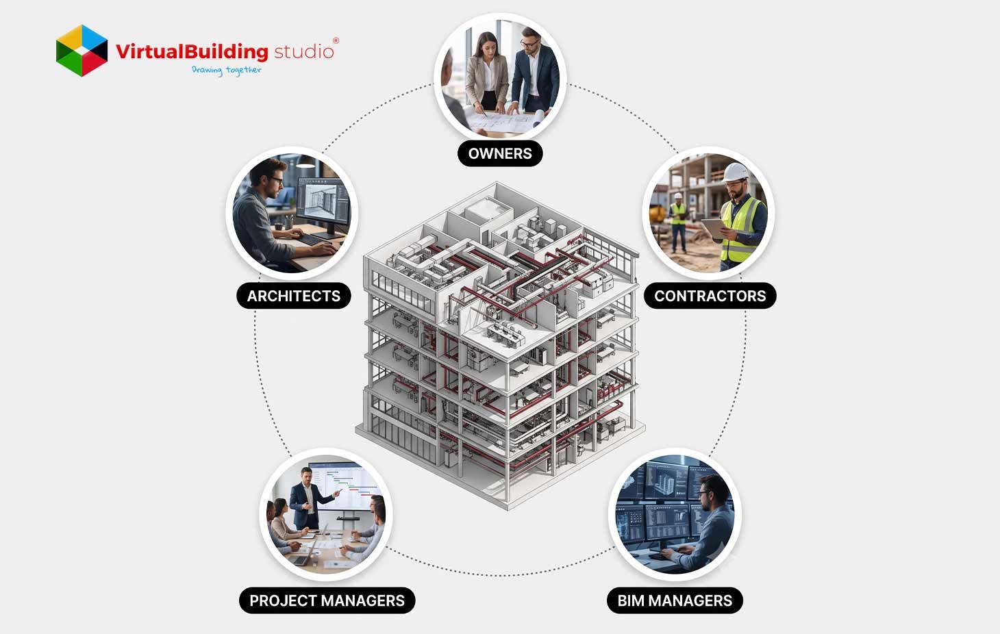
For architects, engineers, contractors, and owners looking to cut rework and avoid repeated mobilizations, the evidence points in one direction. Investing in accurate 3D scan to CAD documentation and Point Cloud to BIM workflows is not a minor upgrade. It is a decision that protects project budgets, reduces schedule risk, and builds a reliable record for every renovation and retrofit project that follows.
Eliminate site re-visits on your next project with our Scan to CAD Service