+1 (409) 800-6601
 contact@virtualbuildingstudio.com
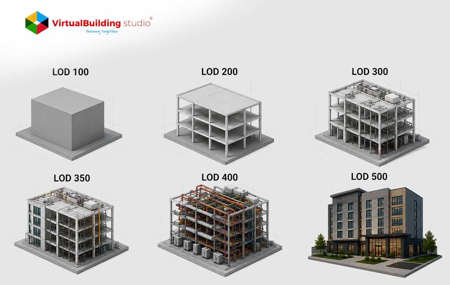
A 3D model can look completely finished long before it actually is. A rendered column or air handlingunit can display full geometry during early design. Its actual structural capacity, fabrication tolerances, and connection details still remain unconfirmed. That gap between visual polish and real reliability creates a genuine problem for project teams. Contractors, estimators and fabricators all need one specific answer: how much can they trust this model right now?
Without that answer, teams start making wrong assumptions. A contractor might treat a schematic-phase duct route as final and order materials against it. That single wrong assumption leads directly to field rework, wasted budget and schedule delays.
The BIMForum’s Level of Development (LOD) Specification defined a framework to solve exactly this problem. LOD in BIM defines exactly how developed a model element's geometry and data actually are. The LOD framework lets architects, contractors, and facility managers share one binding answer to that trust question.
This BIM Level of Development Guide walks through LOD 100 to LOD 500, shows how architectural, structural, and MEP teams apply them differently, and covers the standards that govern them. That shared answer starts with a clear definition of what LOD actually measures.
What Is Level of Development (LOD) in BIM?
LOD in BIM tracks how a model element matures over a project's life. It starts as an abstract space-planning placeholder and ends as a fully field-verified physical component. The American Institute of Architects (AIA) coined this exact concept in 2008, inside the E202 BIM Protocol Exhibit. The AIA later refined it through the G202-2013 form, then again in the 2022 E201 and E202, digital practice documents.
The AIA made one deliberate choice when naming this framework: it avoided the term "Level of Detail." Visual detail and data reliability are not the same thing. Mixing them up is exactly what causes the trust problem described above. So the industry separated BIM levels of detail from Level of Development as two distinct concepts:
- Level of Detail (input metric): It represents graphical richness, like the settings governing Revit level of detail. An element can look extremely detailed and still remain dimensionally unreliable.
- Level of Development (output metric): It measures how much project teams can rely on an element's geometry and data for real decisions, from cost estimating to fabrication.
A few related terms show up alongside LOD in project documentation:
- Level of Information (LOI): LOI includes non-graphical metadata, such as acoustic ratings, structural properties, and warranty data.
- Level of Model Definition (LOMD): It's a UK term combining LOD and LOI into one baseline requirement.
- Level of Information Need (LOIN): The team is codified under ISO 19650 and BS EN 17412-1; LOIN defines the exact geometric, alphanumeric and documentary data a specific project decision requires.
This definition explains what LOD measures. It doesn't yet explain why project teams treat it as a contractual priority. That's the next question worth answering.
Why BIM LOD Is Important in AEC Industry
Without a shared LOD framework, project teams end up making assumptions about model completeness, and those assumptions are usually wrong. A general contractor receiving a schematic-phase architectural model might assume mechanical duct routes are final and start procurement based on incomplete data. That single misread leads directly to field rework and schedule delays.
Formal BIM Level of Development standards prevent this by giving teams a common reference point.
- Standardizing communication: Architects, structural engineers, MEP specialists and owners all speak the same language, when talking about model completeness.
- Reducing contractual risk: Teams incorporate an LOD matrix inside the BIM Execution Plan (BEP) and contract exhibits such as AIA E201-2022. This provides specific authorized uses for each model and protects design professionals if a contractor fabricates off an early stage model.
- Cutting over-modeling: Modeling graphic in detail before it is needed wastes design fees and bloats file sizes.Teams that hold to LOD 100 or LOD 200 targets in early phases spend their modeling budget only where it counts.
- Supporting downstream BIM uses: LOD directly gates what teams can do with a model:
3D coordination: Moving from LOD 200 to LOD 300/350 is what makes automated clash detection reliable.
4D scheduling: Construction sequencing needs LOD 300 or 400 geometry to reflect real installation assemblies.
5D cost estimating: Estimators move from rough $/sq ft numbers at LOD 100 to committed purchase prices at LOD 400.
6D facility operations: Facility managers depend on LOD 500 models loaded with asset tags and maintenance data.
These benefits only work once teams understand what each individual level actually requires. That's where the framework gets specific.
Understanding Each BIM Level of Development (LOD 100 – LOD 500)
LOD Standards in BIM only function because each level carries a precise, documented definition. Here's exactly what to expect at each stage, from BIM LOD 100 to LOD 500.
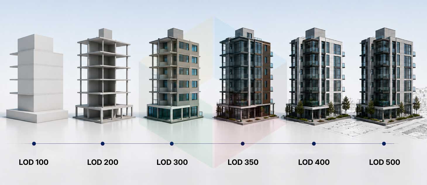
LOD 100: Conceptual Design
At this LOD 100, a model element is nothing more than a generic symbol, a mass volume, or a broad spatial boundary. There's no material data behind it, no structural profile, and no product specification. Any dimension visible on screen works as a placeholder, not an actual measurement.
- Graphical data: Overall massing, footprint polygons, conceptual volumes.
- Non-graphical data: Gross area, target volume, occupancy classification, preliminary performance targets.
Project teams use LOD 100 for feasibility studies, solar orientation analysis, gross area compliance checks, and macro cost estimates like cost-per-square-foot. Nobody should pull exact dimensions off an LOD 100 element for anything beyond that.
- Architectural: A massing block representing a proposed building wing, showing square footage without wall layers.
- Structural: A generic structural zone denoting floor plate depth, without rebar or steel sections.
- MEP: A volumetric box reserving space for a mechanical plant room, nothing more.
LOD 100 answers one question: does this fit the site and the budget? The next level starts answering a harder question: how will this actually get arranged?
LOD 200: Schematic Design (Approximate Geometry)
LOD 200 picks up exactly where LOD 100 leaves off. Model elements become generic systems and assemblies with approximate quantities, sizes, and locations. The geometry turns real at this stage, though it stays generic. A wall shows up with roughly correct thickness, but nobody has specified the stud gauge yet.
- Graphical data: Generic wall thickness, floor slab contours, structural column layouts, preliminary duct routing.
- Non-graphical data: Generic material categories, preliminary structural grades, approximate assembly types.
Teams use LOD 200 for schematic design review, checking spatial clearance and early quantity takeoffs.
- Architectural: Interior partitions as generic solids with corrected overall thickness.
- Structural: Wide-flange steel columns at approximate grid intersection points.
- MEP: Main HVAC ducts modeled as rectangular solids, without flanges or turning vanes.
LOD 200 gives the building its rough shape. LOD 300 turns that rough shape into something teams can actually build documents from.
LOD 300: Detailed Design (Precise Geometry)
At LOD 300, elements become accurate in quantity, size, shape, location, and orientation. Every element also ties to the project's actual coordinate origin. That detail matters: teams can measure directly off the model instead of relying on written callouts.
- Graphical data: Exact component layers in walls, precise structural profiles, actual MEP equipment footprints and connection ports.
- Non-graphical data: Thermal performance values, structural ratings, fire ratings, OmniClass/UniFormat tags.
LOD 300 is the standard level for construction documentation. Teams typically prepare drawings, schedules and elevations straight from LOD 300 models. This is also the level where general clash detection starts producing meaningful results.
- Architectural: An exterior wall with exact layering, such as 5/8-inch gypsum board, 3-5/8-inch steel studs, 1-inch rigid insulation, and 4-inch face brick.
- Structural: A concrete beam with right dimensions and cast-in sleeve openings for MEP.
- MEP: An air handling unit with exact manufacturer dimensions and connection points.
LOD 300 tells a contractor what the design intends. It doesn't tell them how the pieces physically connect to each other. BIMForum built LOD 350 specifically to close that gap.
LOD 350: Construction Coordination (Precise Geometry with Connections)
BIMForum introduced LOD 350 to fill the exact space between design intent and fabrication. At this level, elements gain explicit interface geometry. The model now shows how a component physically connects to the systems around it, not just what the component looks like alone.
- Graphical data: Support brackets, backing plates, slab edge angles, MEP hangers, seismic bracing, penetration sleeves.
- Non-graphical data: Fastener load ratings, connection specifications, trade installation responsibilities.
LOD 350 is the benchmark for detailed multi-trade clash resolution and pre-construction sign-off. It lets general contractors and trade specialists catch structural bracing clashing with ductwork before anyone shows up on site.
- Architectural: A curtain wall with embed plates, anchor brackets, and fire-stop seals.
- Structural: Steel columns with base plates, anchor bolts, stiffeners and splice joints.
- MEP: Chilled water pipes with insulation thickness, hangers, and seismic trapeze assemblies.
Once connections get resolved at LOD 350, the next step is turning that coordination into something a fabricator can actually cut and weld.
LOD 400: Fabrication Ready Geometry
LOD 400 elements become vendor-specific, carrying complete fabrication, assembly, and installation detail. The geometry gets precise enough that shop teams can feed it directly into CNC steel cutters or duct spooling machines.
- Graphical data: Weld symbols, individual rebar with bend radii, sheet metal flanges, bolt threads, shop assembly cutouts.
- Non-graphical data: Manufacturer part numbers, order codes, fabrication delivery sequencing, committed purchase costs.
LOD 400 authorizes off-site prefabrication, shop drawing extraction, procurement and detailed 4D logistics planning plus crane capacities and shoring layouts.
- Architectural: Precast facade panels with lifting loops, panel connections and sealant backer rods.
- Structural: A concrete column with complete rebar layout, tie spacing and embedded plates.
- MEP: Ductwork spools with exact sheet metal thickness, flanges, and shop piece IDs for plasma cutting.
Once fabricators install these components on site, one transformation still remains: capturing what actually got built, not just what got planned.
LOD 500: As-Built Model
LOD 500 flips the logic behind the four BIM modeling levels before it. LOD 100 through 400 represent design intent and construction planning. Contractors verify field conditions to prepare LOD 500 models that correctly represent reality, not the design intent.
- Graphical data: Geometry adjusted to match field conditions, laser-scan point cloud alignments, verified clearances.
- Non-graphical data: Asset tracking IDs, serial numbers, warranty dates, maintenance schedules, COBie data, commissioning records.
Facility teams use LOD 500 exclusively for facility management, asset tracking, capital planning and digital twin deployment.
- Architectural: As-built floor plans with verified dimensions and installed hardware schedules.
- Structural: A foundation model that represents actual pile cap coordinates and post tensioning anchor locations.
- MEP: A commissioned mechanical model with barcode tags, serial numbers, and balanced flow data.
That covers the full spectrum, from placeholder mass to field-verified asset. Seeing all six levels side by side makes the differences easier to compare.
LOD 100 to LOD 500 – Quick Comparison
This table shows LOD as a clean, linear progression. Real projects, though, rarely move that way, and understanding why matters just as much as knowing the definitions.
LOD Requirements Across Project Phases
A common assumption trips up a lot of teams: that an entire building model advance through LOD levels uniformly, all at once. It doesn't. A BIM model is a mix of elements progressing at different speeds depending on discipline priorities.
During Design Development, for instance, structural framing might already be at LOD 350 because long-lead steel needs to go out for procurement early. Meanwhile, interior casework is still sitting at LOD 200, and specialty MEP equipment hasn't moved past LOD 100. All three coexist in the same model, at the same phase, at three different LOD levels.
The progression typically maps to project phases this way:
- Pre-Design or Master Planning: LOD 100 across the board.
- Schematic Design: LOD 200, with generic placeholders for major systems.
- Design Development: LOD 300, dimensioned and positioned accurately.
- Construction Documentation: LOD 350, with connections and interfaces resolved.
- Procurement or Fabrication: LOD 400, owned by trade contractors.
- Handover or Closeout: LOD 500, field-verified and loaded with O&M data.
Phase alignment explains the timeline. But each discipline also applies these levels in its own way, and that's worth breaking down separately.
BIM LOD for Different Building Disciplines
Architectural, structural, and MEP teams follow the same six BIM LOD levels. They just apply them to entirely different problems, whether through in-house staff or outsourced BIM Modeling Services.
Architectural BIM LOD
Architectural BIM LOD tracks spatial enclosures, partitions, and building envelopes. Firms delivering Architectural BIM Services start at LOD 100 with simple massing that shows overall volume without wall layers. At LOD 200, partitions become generic solids with approx thickness. Real-world layers like gypsum board and stud cavities with openings are modeled at LOD 300.
The curtain wall interface details including embed plates and firestopping are at LOD 350. LOD 400 delivers shop joinery and precast panel lifting hardware. LOD 500 closes the loop with field-verified dimensions and finish codes.
Structural BIM LOD
Structural BIM LOD represents foundations, reinforcement, framing and connections. Engineers start at LOD 100 with spatial volume allowances for core walls. At LOD 200, they place generic wide-flange shapes at approx grid intersections. LOD 300 sizes members accurately along with sleeve openings for MEP.
LOD 350 adds base plates, stiffeners, and splice joints. LOD 400 articulates full rebar geometry and weld symbols ready for CNC cutting. LOD 500 records verified pile cap coordinates and actual concrete test data.
MEP BIM LOD
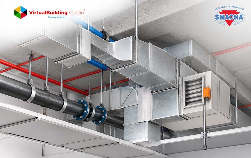
MEP BIM LOD represents HVAC, electrical, plumbing and fire protection systems. Teams keep space for utility plants at LOD 100, then showcase main duct and pipe routes as generic solids at LOD 200.
LOD 300 sizes ductwork and piping to actual manufacturer footprints. LOD 350 adds insulation thickness, seismic hangers, and penetration sleeves. LOD 400 delivers full sheet metal spool models ready for plasma cutting. LOD 500 populates commissioned models with barcode tags and flow test data.
Knowing what each discipline expects at every level helps teams plan correctly. It doesn't automatically stop them from misapplying the framework once the project gets moving.
Common Mistakes When Using BIM Level of Development
Even with LOD standards written into contracts, teams still misapply them regularly, and the fallout follows a predictable pattern: cost overruns, bloated files, and disputes over who owed what.
- The uniform LOD fallacy: Demanding an entire model hit LOD 400, including furniture and minor trim, inflates modeling costs for no practical benefit.
- Confusing detail with development: A Revit element can look highly detailed and still not be dimensionally reliable, only its assigned LOD confirms that.
- Treating the LOD matrix as static:If you leave the Model Element Table frozen after kickoff, you will have gaps as to who owns what element at each phase.
- Fabricating from LOD 300 models: Subcontractors sometimes go directly from design-intent geometry to manufacturing without thinking about the tolerances that exist only at LOD 400.Components then arrive on site that don't fit.
- Blanket LOD 500 requirements: Field-verifying every stud and footing wastes resources. Teams should target LOD 500 only at assets facility managers actually need to track.
Avoiding these mistakes takes more than good intentions. It requires reference points, which published LOD standards already provide.
The BIM LOD Standards and Industry Guidelines
AIA Digital Practice Documents remain the backbone of LOD in North America. E202-2008 introduced the original five-tier system and the Model Element Table. G202-2013 sharpened the focus on authorized reliance. The 2022 E201-E202 series added modern digital rights and liability language.
BIMForum's Level of Development Specification builds on the AIA base. BIMForum added LOD 350 as a sixth tier to the original five levels the AIA defined, organizing definitions through CSI UniFormat 2010 and OmniClass. It also provides visual illustrations for hundreds of components across every discipline, which makes it the most practical day-to-day reference for project teams.
ISO 19650 and BS EN 17412-1 point toward where the industry is heading. Instead of rigid numeric tiers, the Level of Information Need (LOIN) framework asks clients to define exactly what geometric, alphanumeric, and documentary data a specific deliverable needs.
Knowing these standards is one thing. Applying them correctly on a live project is the harder skill, and it comes down to a few repeatable practices.
Best Practices for Selecting the Right LOD
Getting LOD right means balancing model usefulness against modeling cost, and teams set that balance early, not after the fact.
- Build a project-specific LOD matrix: Map every element, classified by UniFormat or OmniClass, against every project phase inside the BEP.
- Assign Model Element Authorship explicitly: One person owns each element at each phase, whether that's the architect for partitions or the fabricator for connections. This helps in avoiding duplicate modeling across all the trades.
- Match LOD targets to delivery method: In Design-Bid-Build the design teams end at LOD 300 or LOD 350 and the speciality contractors create separate shop level LOD 400 models. In Design-Build or IPD, fabricators join early and models move straight into LOD 350 or 400 together.
- Run automated model audits: Tools like Solibri or Navisworks catch LOD compliance issues before milestone sign-off, so nobody discovers a mismatch after the fact.
These practices keep LOD useful today. The framework itself, though, is evolving, and it's worth knowing where it's headed next.
Future of LOD in Building Information Modeling
Laser scanning, AI and cloud data management are reshaping how teams apply LOD in practice.
- Shift toward LOIN: The industry is gradually moving from fixed numeric tiers toward dynamic, machine-readable Level of Information Need definitions that pull only the data a specific decision actually requires.
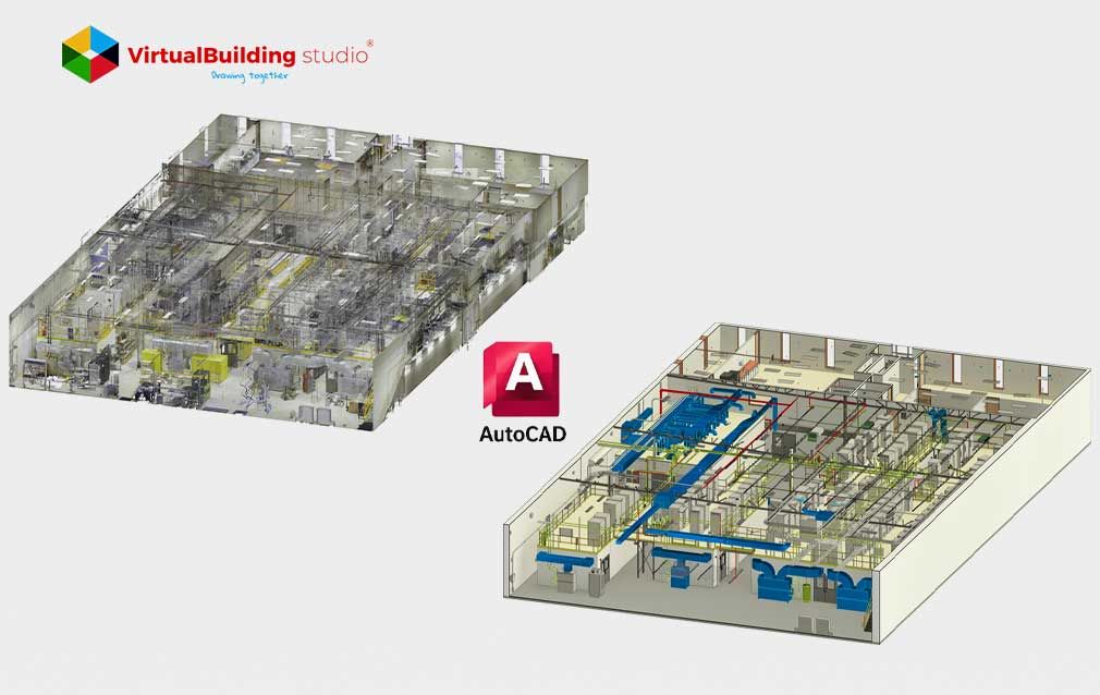
- Scan-to-BIM automation: Teams now use LiDAR scanning and photogrammetry to compare point cloud data against design models automatically, speeding up the path to verified LOD 500 status.
- AI-based LOD Auditing: Machine learning tools are increasingly auto tagging the model elements with the right LOD class according to geometric completeness.
- LOD as the digital twin foundation: Facility teams bind real-time IoT and building management data directly to field-verified LOD 500 geometry to run functional digital twins.
These shifts don't replace the fundamentals covered in this guide. They build on them, which is exactly why understanding LOD 100 through 500 remains essential groundwork.
Conclusion
LOD gives the AEC industry something static 2D drawings never provided: a precise, enforceable answer to how much a model can be trusted at any given moment. From the placeholder massing of LOD 100 to the field-verified precision of LOD 500, each level answers a specific question at a specific project stage.
Getting LOD right protects design fees, prevents field rework, and keeps architectural, structural, and MEP teams working from matching expectations. As the industry moves toward ISO 19650 and LOIN, the logic behind LOD Standards in BIM isn't disappearing. It's getting sharper, and teams that understand it now will adapt fastest as it evolves.

Get Expert BIM Services That Deliver the Exact LOD Reliability Your Project Needs