

Site Utilities 3D Modeling
Built the full site utility network in Revit across 251 residential units using available references and applicable standards.

LOD 300 BIM modeling for drainage and water systems delivered for a 1,054,670 sq. ft. residential development within tight timelines using limited inputs.
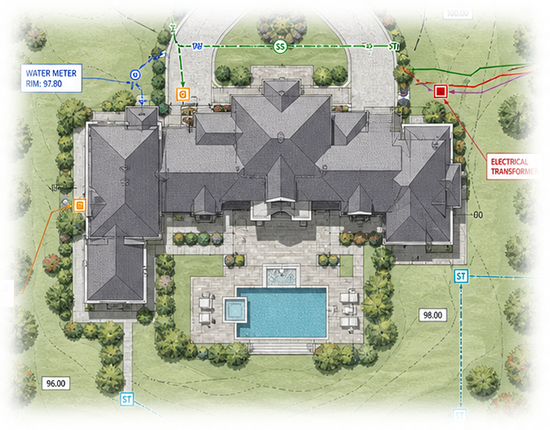
A site utilities firm needed expert BIM support for a large residential development spanning over 1,054,670 sq. ft. in Caldwell, ID, USA. The project covered complex drainage and water main systems across 251 units.
With only partial inputs and a 10-day deadline, our 3-member team delivered an LOD 300 Revit model. All systems were accurately modeled, slopes were maintained, and files were delivered on time.
 Project Type Residential Building
 Level of Development LOD 300Project Area 1,054,670 Sq.Ft.
 Manpower Used 3 Resources
 Location Caldwell, ID, USA
.jpg)
Site utility modeling was delivered in Autodesk Revit so outputs aligned with the client's existing BIM workflow.
 Autodesk Revit
From partial architectural references to a complete LOD 300 site utility model with accurate slopes and depths.
.jpg)
Limited inputs, strict depth compliance, and a 10-day deadline made accurate site utility modeling especially demanding.
The project required full site utility modeling within a strict 10-day turnaround window.
Only one-third of the architectural model was shared, limiting reference data for accurate modeling.
The drainage network included intricate trench systems and catch basin layouts needing careful coordination.
The water main had to run exactly 48 inches below the top of the asphalt throughout the site.
Maintaining vertical offset while tracking the asphalt slope added significant technical complexity to the model.
Only partial architectural input was available when modeling began.
Modeling interconnected trench and catch basin systems with correct slopes.
Delivering a complete and accurate model within a 10-day project window.
Advanced BIM tools and disciplined modeling standards maintained accuracy despite limited inputs and strict compliance requirements.
Built the full site utility network in Revit across 251 residential units using available references and applicable standards.
Modeled intricate trench systems and catch basin layouts with correct slopes and coordinated connections.
Maintained a consistent 48-inch offset below the asphalt surface while tracking variable site slopes.
Precision Site Utility Delivery Under Pressure
Our team leveraged advanced BIM tools and professional expertise to model complex site utilities with precision. Despite limited inputs, we maintained high accuracy, met compliance requirements, and delivered the model on schedule.
Input Review and Scope Confirmation
Input Review and Scope Confirmation
Input Review and Scope Confirmation
Input Review and Scope Confirmation
Drainage Network Modeling
Drainage Network Modeling
Drainage Network Modeling
Drainage Network Modeling
Water Main Depth and Slope Alignment
Water Main Depth and Slope Alignment
Water Main Depth and Slope Alignment
Water Main Depth and Slope Alignment
Utility System Coordination and QC
Utility System Coordination and QC
Utility System Coordination and QC
Utility System Coordination and QC
LOD 300 Model Validation
LOD 300 Model Validation
LOD 300 Model Validation
LOD 300 Model Validation
Final Revit Delivery
Final Revit Delivery
Final Revit Delivery
Final Revit Delivery
Accurate site utility modeling delivered on schedule despite partial inputs and demanding depth requirements.
Dedicated offshore modeling support reduced delivery cost versus expanding the internal team for a 10-day sprint.
The complete LOD 300 utility model was delivered within the 10-day project window.
A focused three-person team maintained modeling momentum without back-and-forth delays.
Water main depths, drainage slopes, and catch basin layouts were validated before final submission.
Let's discuss your requirements and see how our expertise can help on your next project.